1.
Plastikmodellbauclub Nürnberg e.V.
|
|
|
|
|
|
| |
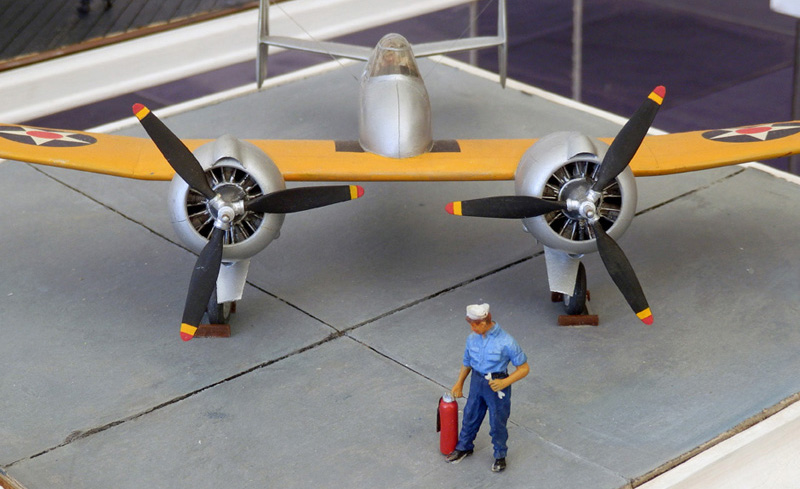
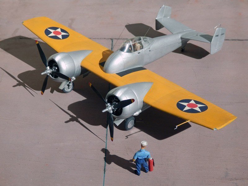
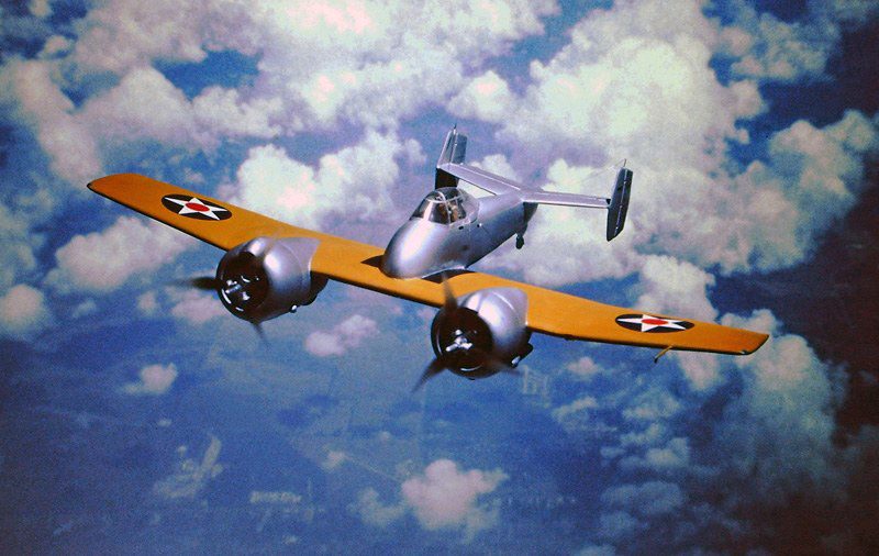
| Grumman F5F-1 Skyrocket, 1:48 scratch
built without any kit or accessory parts |
The G-34 design for a
shipboard fighter with a
takeoff weight under 10,000 pounds (4,536 kg), presented to the U.S. Navy by
Grumman Aircraft Engineering Corporation in 1938, was unlike anything seen
before. Fighter planes of the time were typically single-engine biplanes with
fabric-covered wings and rudders and featured twin 7.62 mm machine guns. In
contrast, the unofficially named "Skyrocket" was all-metal except for the
rudders and had two Wright R-1820-40/42 nine-cylinder radial engines of 1,200 hp
each, whose propellers rotated in opposite directions, thus not only balancing
the respective torque of one engine but also promising high speed and climb
performance. A striking feature was the extremely short nose, which provided an
excellent view of the landing signal officer and deck. Two Danish 23-mm Madsen
guns were provided as armament.
The design was convincing, and a test specimen
under the designation XF5F-1 was ordered on June 30, 1938. The first flight on
April 1, 1940, was thoroughly positive, but also revealed inadequate cooling of
the engines and a main landing gear in need of revision. The modification of the
engine cooling system took until July 15, 1941, because the US Navy's
modification requests also had to be taken into account: A flatter cockpit
canopy and, because of wartime events in Europe, replacement of the Danish
machine guns with four domestic cal. .50 (12.7 mm) machine guns, which required
a significantly lengthened nose. In addition, there were modifications to the
engine cowlings, extended engine nacelles for improved airflow, and spinners for
the propellers. This dragged on until January 15, 1942. By this time, Grumman
already had several other new orders, including the XF7F Tigercat based on the
XF5F, so further test flights and rework of the landing gear were not top
priorities. After two landing gear failures on February 3, 1942, and May 18, 1942,
and a belly landing on December 11, 1944, the XF5F-1 Skyrocket was removed from
the register and later scrapped. Measured flight data: Top speed 383 mph
(616.379 km/h), rate of climb 4,000 ft/min (1219.2 m/min).
The model:
In 1993 there was no kit available for the F5F-1 Skyrocket. In
such a case, the experienced modeler looked in his "spares box" for usable parts
and / or cannibalized other models. Since I didn't find anything useful on my
end, that would have meant buying two Monogram F4F Wildcat kits for the
propellers alone. But if you are able to build cockpit canopies yourself (without
balsa wood blocks), you should be able to do the same for the fuselage and
engine nacelles. That's what I thought and decided to make it 100 percent right
away to show that it can be done without kit butchery. Sounds difficult, but it
wasn't at all. Required some thought and patience, but it was also a lot of fun.
To prove that something like this is possible, in the necessary brevity:
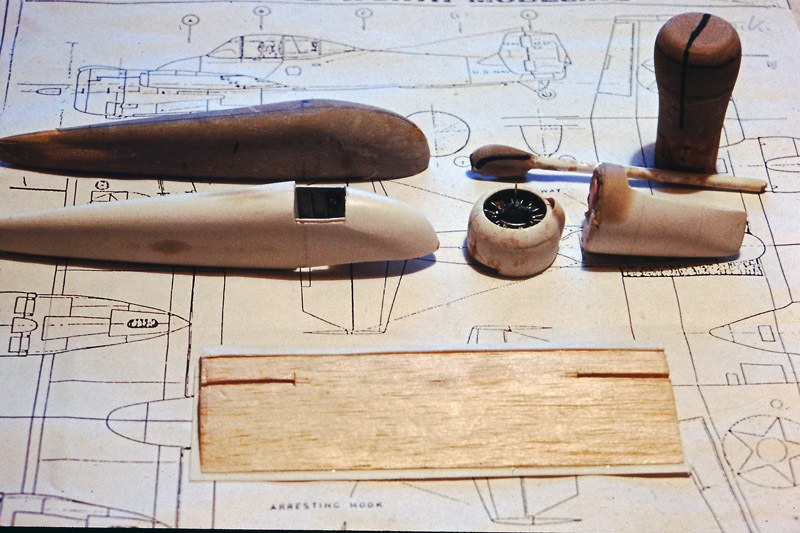
Construction stage 1
In the background, the 1:48 scale plan minus the
material thickness of the plastic. On the top left the mold for the fuselage
made of polyester putty, on the right the molds for the engine nacelles.
Why there are still people today who think you have to carve balsa wood for a
mold, I don't know. Nowadays there is polyester putty, to be found in DIY stores
at car accessories, which can already be roughly cut to size after mixing with
4% hardener and can be sanded and polished to a high gloss after complete
hardening (alternatively I could have used "FIMO" modeling clay, but here you
can't apply a second layer if you made a mistake).
Before that, the already finished parts. The plastic was first softened over a
toaster and then pulled over the mold in a smooth motion. A parting line drawn
on the mold part and a scalpel helped remove the excess. Strips glued to the
inside helped join the two parts (see, for example, model T2V-1). Below you can
see the center section of the wings, profiled balsa, front and bottom already
planked and cutouts for sloping parts to attach the outer wings.
The clear PVC cockpit canopy, not
visible here, was made according to the same principle (see also Modeling ABC
page C). As far as handling during "toasting" is concerned, two strips fastened
with thumbtacks are sufficient for parts that need little deformation; for
others, such as the F5F cockpit canopy here, it is better to cut out the
horizontal shape from thin plywood with some allowance for the thickness of the
PVC material and fasten the clear PVC to it with thumbtacks. While heating over
the toaster, turn occasionally until the PVC begins to shine and become limp.
Now pull over the mold with even pressure, PVC side down. If you have already
attached a "foot" at the bottom when building the mold (material doesn't
matter), your hands will have plenty of room to move down when pulling.
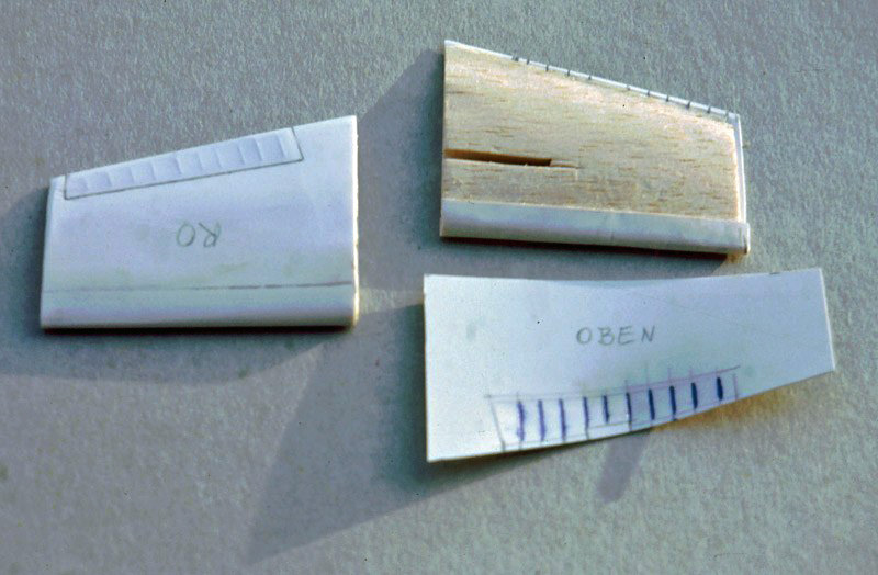
Construction stage 2
Building the wings: core balsa, sanded to profile, planked with
thin plastic. First the nose section was molded, i.e. plastic, attached to two
ledges, softened and placed around the wing nose; cut off excess and attach
molded section with super glue. The following parts need to be done quickly, as
the wedge-shaped chamfered trailing edges get a thin layer of plastic glue, but
the rest of the insides get super glue. The wing tips are clear polystyrene,
which saves having to insert the lights separately. Replicating the fabric
covering was simple: mark the ribs on the inside and then emboss with a
ballpoint pen, mark the rudder outline on the outside and engrave after planking.
Real sheet metal joints are very fine lines, so only drawn with a scalpel tip
here. That's all to it. Real planking is as tight as a drumhead and does not sag
at all like waves.
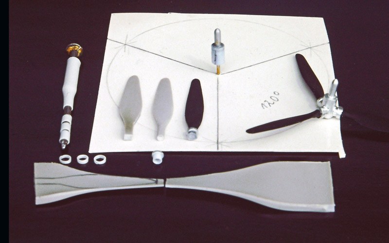
Construction stage 3:
The photo above shows how the propellers were
made (the finished part on the right). For the propeller blades plastic of
suitable thickness was carefully softened over the toaster. After a second or
two to cool, both ends were pulled apart, twisting them slightly against each
other. This not only makes the propeller blade thinner towards the tip, but also
gives it the pitch common to all propellers, i.e. the angle of attack is greater
at the hub than at the tip (zero there). The shape is marked with a template,
cut out, profiled, finished. For the fastening clamps, I found a nail of
suitable thickness, slid a piece of pipe over it, softened it over a candle
flame, and then pulled it apart until the material was tight against the nail (same
procedure for the fixed part of the landing gear). The hub of the propeller was
created from an assembly of pieces of tubing pushed into each other to the
diameter of the later propeller axis. After the position of the propellers was
marked using a template and appropriate holes were drilled, the propeller blades
could be aligned and glued. A thin tube with a plug so that it can be rounded
off at the front then completes the whole thing- That's all it took, almost
child's play, no resin part, no model stripping required.
Construction stage 4
Unfortunately I forgot to take pictures of the engines and
engine nacelles. Of course, nowadays you would buy finished resin parts for the
motors, but they were not available and besides, I wanted to show that it can be
done without. In principle, it's quite simple: First, wrap a thin copper wire
strand around a core (in my case, a suitably made sprue rod, tubes would also
work, of course). For better handling, make the core a little longer than needed,
fix the wrapping with superglue on the back. Then drill a fine hole each for the
ignition cable and cut off after painting result. Engine case: pipe material of
suitable thickness, closed at the front by a washer. Mark cylinder spacing of 40
degrees each, then align and fasten cylinders. Front gearbox part: drilled
through solid material, roughly shaped, attached to a screw by two nuts, and
shaped to final shape by drill and sandpaper, where a previously drawn circle
was helpful. After removing the screw, narrow the hole to the cross-section of
the propeller axis, as in the case of the rear part, by inserting thinner pieces
of pipe (the same applies to the propellers, which are not fitted until the
end).
The distributor ring was made from a piece of
sprue, softened over a candle flame, pulled apart and immediately wrapped around
a brush handle (if necessary, glue two halves together). As a guide for the
ignition cables, grooves were filed on the back. Ignition are cables copper wire,
at the lower end with a pushed on short piece of thin tube material, fixed with
superglue. Pushrods likewise parts of a thinly drawn sprue. Paint both before
attaching.
| |
Construction stage 5
The engine nacelles were made in the same way as the
fuselage, but from horizontally split halves. To make them fit the wing
profile, one part was cut out by eye and the rest was pushed to and fro on
the sandpaper placed on the wings until everything matched. The same
procedure was followed for the air intake on the engine cowling. It
consists of the front ring and two semi-circular pieces behind it. As with
the fuselage, thin tabs on the insides ensured that no steps were created
during gluing. |
| |
| As for the cockpit and
landing gear wells, any attempt to detail them would have produced a
fictitious result. If there were corresponding photos, they have not
been published. But this was not a major problem, because with the
canopy closed, virtually everything is covered by the pilot figure. In
the cockpit, therefore, only a rudimentary instrument panel and a
bulkhead with seat and crossbar behind/above it were installed (there,
as was usual in the Navy at the time, the belts ran over it). The
housing on the back of the fuselage behind it is ground solid. The pilot
is self-built except for the head and hands of a Verlinden figure.
Cockpit canopy as usual self-drawn from clear PVC (for principle see in
principle see modeling-ABC, page C). |
| |
| Antenna:
Never, ever a thinly drawn sprue. Scale thin, it
is difficult to work with, can not be dusted, later becomes brittle and
breaks by itself. I have something much better. Easy to work with, can
take a light bump, and lasts forever. And costs nothing! - It was again
a thread from a piece of my wife's tights, which can also be divided
into single threads to achieve the required thinness. If you divide this
partial thread again, this produces the lead off into the fuselage, laid
over the already stretched actual antenna thread. Both ends were
anchored with a plug in the previously drilled hole in the fuselage (the
excess was carefully cut off after drying). Plastic glue was sufficient
here, otherwise superglue is required. - So don't laugh, but try it out. |
|
| |
| The main landing gear added
after the "flight shots" consists of a cranked and appropriately shortened
nail, with the tube pushed on and attachments analogous to the illustration
for construction section 3, because metal looks better than painted. For the
wheels, plastic of suitable thickness was first roughly shaped round, then
fastened with bolts and nuts in a drill press and ground into the shape of
the wheel based on the drawn circle. Another circle inside indicated where
the transition from the tire to the hub had to be carved out with a scalpel.
The rear wheel was made from a ball of "FIMO" modeling
clay, first pressed a little flatter and then using a pressed-in tube to
form the separation between the tire and the hub. |
| |
| Colors: In 1938, U.S. Navy
aircraft had an aluminum-colored protective paint on the fuselage and tail,
wings on the top "Orange Yellow" , on the leading edges 5% around to the
aluminum-colored underside. Interior color was left to each manufacturer. "Interior
Green" was introduced much later (see "Colors of the US Navy 1941-1945"). I
assumed that at that time the protective paint was also applied to the
cockpit interior, as seen in a factory photo of the Douglas TBD Devastator,
instrument panel black. In the model these were the colors Humbrol 99
aluminum, the others Revell: yellow mixed with a dab of red, cylinders
according to the production of gray cast iron light gray, not chrome,
pushrods black, ignition cables aluminum, gearbox housing dark gray. |
| |
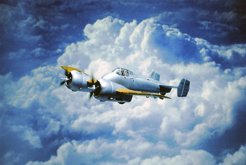
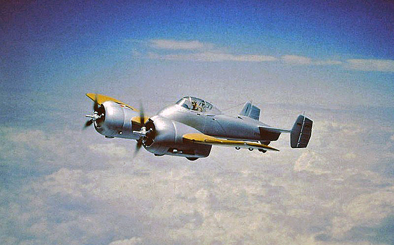
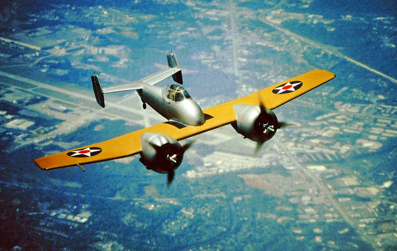
| About the photos: All "flight
shots" on slide film, so not post-edited. |
| |
|
|