|
|
|
1. Plastikmodellbauclub Nürnberg e.V. |
|
|
| back to Modellfotos 2 |
| Model and photos by Gerd Busse |
|
|
|
|
|
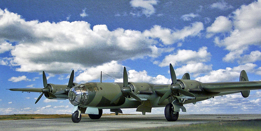
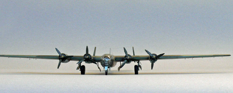
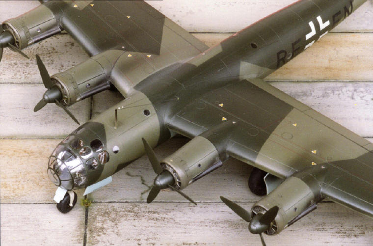
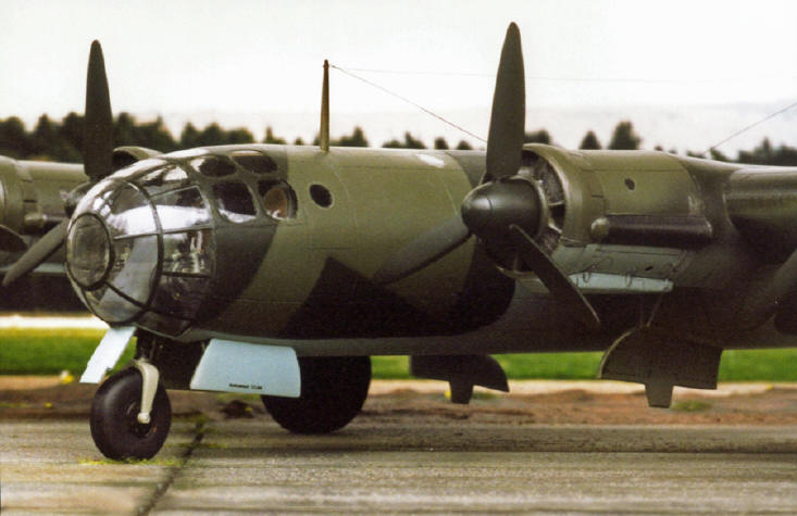
Messerschmitt Me 264 V1, Special Hobby, 1/72 |
|
|
The original:
During WWII, the four engined Me 264 was designed in such a way that it could reach the east coast of the US. This requirement resulted in an aircraft with a high aerodynamic quality which means a slender stream line fuselage and wings with a high aspect ratio allowing the aircraft to fly at a low power.
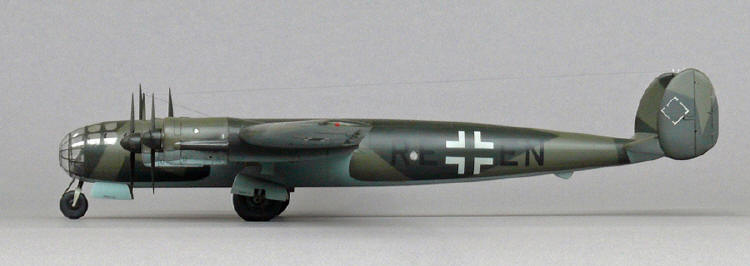
Actually, only one prototype was built, the Me 264 V1 (RE+EN) WerkNr. 264000001, which made its maiden flight on Dec 23rd, 1942 in Augsburg with factory pilot Karl Bauer at the controls. After its second test flight the aircraft was flown to Lechfeld on Jan 22nd 1943. Thereafter the four engines Jumo 211 were replaced by BMW 801 with which the first test flight was performed on April 16th, 1944. During an allied bomb raid on July18th, 1944 the aircraft was damaged beyond repair. This way the project Me 264 came to its end (data taken from articles published by Griehl and Green
).
The model:
Luckily, the
mistakes of this model produced by Special Hobby in 2002 can be eliminated if one is aware of them ahead.
F
uselage:To avoid a tail sitter the nose section of the model should be filled with as much lead as possible.
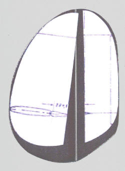
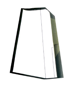
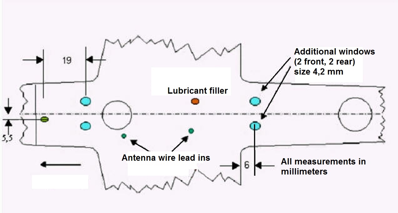
Both vertical and horizontal stabilizer of the model should be cut from the parts contained in the box according to the pictures where the shaded areas indicate the material that needs to be removed. The four missing circular windows are made according to the drawing
|
|
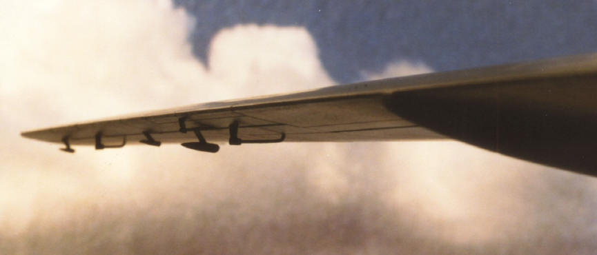
Wings:
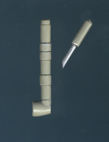
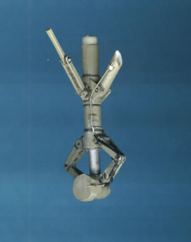
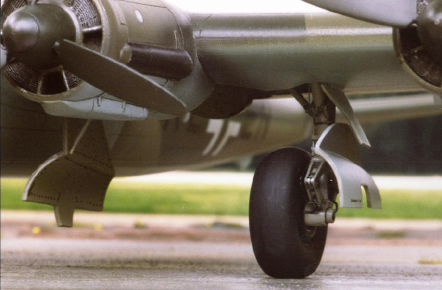
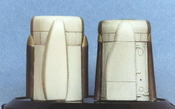
Landing gear:
|
|
|||||
|
|
|
|||||
|
|
|
|||||
|
|
|
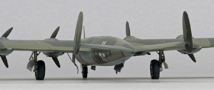
Cockpit:
Due to the highly transparent cockpit area, some detailing is advisable, i.e. rudder pedals /Extratech No. 72120) and bomber seat belts (Eduard No 72307). The cables in front were applied according to photos (Sengfelder). This detailing can be clearly seen tbrough the glazed cockpit cover
.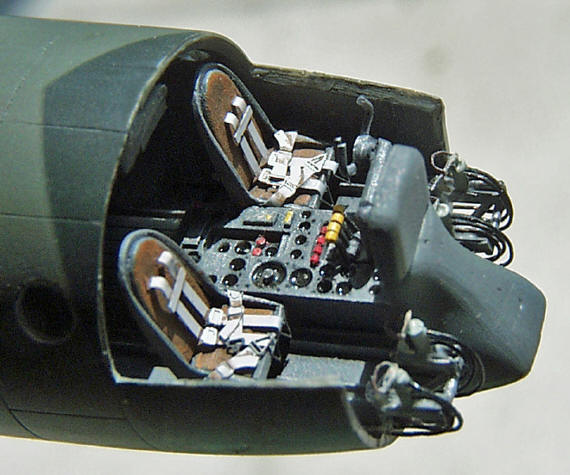 |
 |
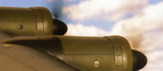
Engines:
 |
|
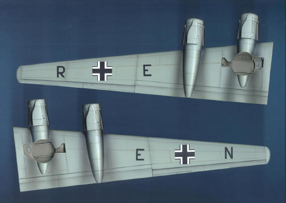
Location of the "Balkenkreuz":
According to RLM rules the cross underneath each wing is in the middle between the wing tip and the outside of the engine cowling; the letters are in the middles in between. On the upper sides of the wings, the distance is 2 meters from the wing tip.
 |
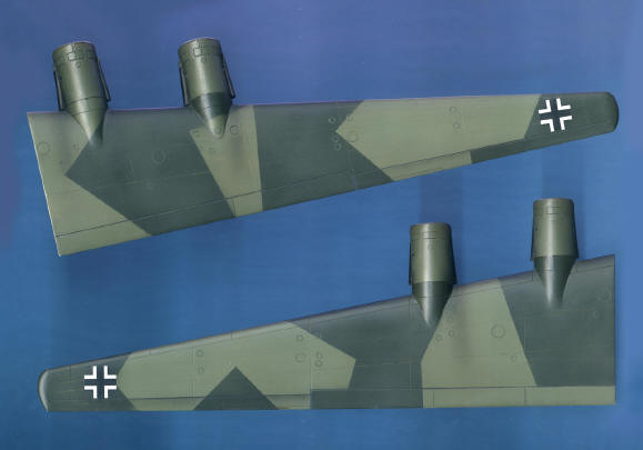 |
Colors:
Gunze paint is used for camouflage: blue RLM 65 (underneath) and greens RLM 70 and RLM 71 for the splinter pattern on upper surfaces.
|
|
|
|