 |
| 1. Plastikmodellbauclub Nürnberg e.V. | |||
|
|
|
Lockheed T2V-1 Sea Star, Scratch 1/48
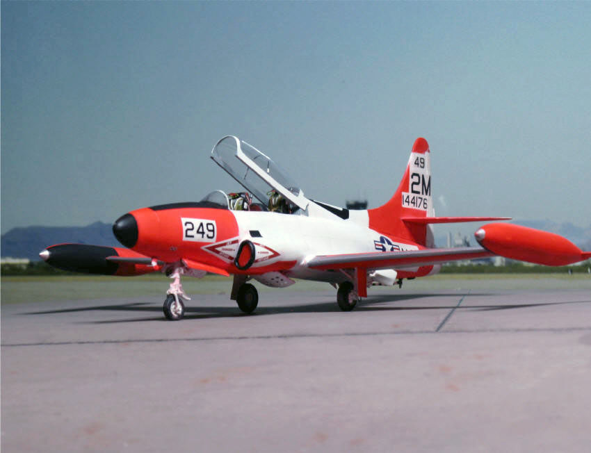
The original T2V-1 (1962: T-1A):
The succes of the T-33 jet trainer in the USAF and the lack of a comparable aircraft in the US Navy made Lockheed to conceive an aircraft suitable for aircraft carrier use. To provide a better view for the instructor pilot the seat was raised resulting in a sizeable fairing aft of the cockpit and a very much enlarged empennage. The engine was changed to the stronger Allison J-33A-24A, and a - then new - boundary control installed. Lockheed won a contract in May 1954, after carrier suitability test and unevitable modifications the new aircraft - called Sea Star - went into squadron use in 1958. But its service life was short. 1960 the Sea Star was supplanted by North Americans' superior T2J Buckeye although quite a few soldiered on as station hacks or for internal training.
 |
 |
|
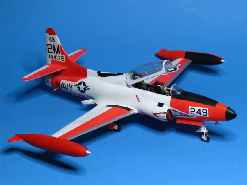
The model: In 1/48 there is still no kit available. Having built the F5F-1 entirely from scratch (see F5F-1 model) I expected no unsurmountable difficulties converting a T-33 into a T2V-1 Sea Star by adding a scratch hump and a new empennage (homemade canopy as usual). So I bought an old Academy T-33 kit. |
|
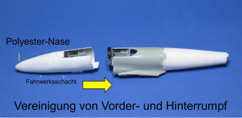
I should have had a closer look! - The real T2V-1 had a 26,6 in. insert in front of the wings and 12 in. after them. Was to be made in model form too. If the T-33 horizontal and vertical tail was removed there wasn't more left than the lower half. Removing the T-33 air intakes left some sizeable holes to be filled somehow. So altogether making a complete fuselage (definitely no wood) from the outset seemed to be more practical , and, not to forget, also new air intakes were needed. Taking care of some other differences finally only the kit wings, tip tanks, nose gear well and doors and the main wheels could be used. |
|
I don't think somebody will be nutty enough to make a model the same way. But some of the construction details may be helpful in other ways. Modeling without resin parts is possible and cheaper. If somebody can't resist the urge to get a 1/48 Sea Star model (in 1/72 Sword now offers one) referring to "Naval Fighters No. 42 by Steve Ginter is recommended though in the planform drawing the horizontal tailplanes are of different size. |
|
||||||||||||||||||
|
||||||||||||||||||
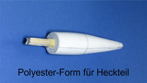
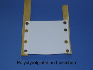
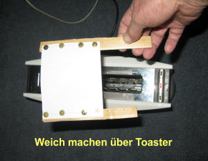
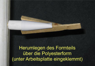
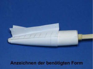
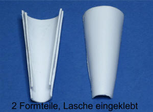
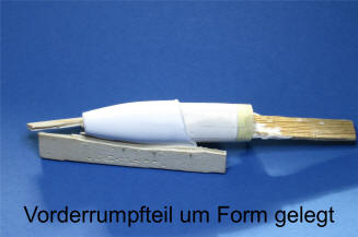
| Plastic parts: For forming the fuselage shells plastic sheet of 0,3 millimeter thickness was just right. As described in my page C "cockpit hoods scratch" plastic of slightly larger size than needed was softened over a toaster and then laid over the form with gentle pressure (not pulled with force!). This is made easier (and good for your hands) by application of wooden strips at both ends. If all went well pencil lines show where to cut. Repeat procedure for the other fuselage half. Narrow strips fixed lengthwise on one inside help to achieve a firm joint. The front half of the fuselage is made the same way though no need for strips in vicinity of the cockpit and wheel well. | ||||||||||||||||||
|
||||||||||||||||||
|
||||||||||||||||||
|
||||||||||||||||||
|
||||||||||||||||||
|
||||||||||||||||||
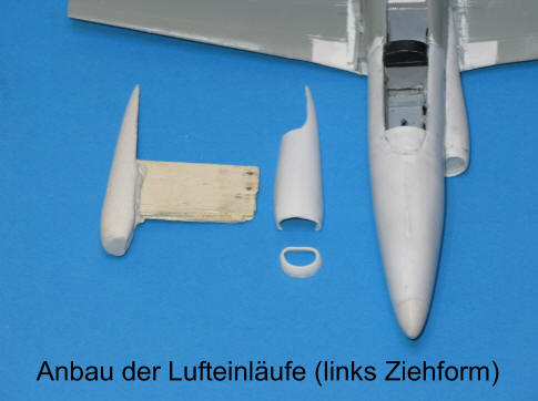
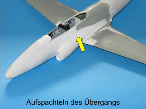
| Air intakes: In principle made the same way as the fuselage, but as they were slighty offset to the fuselage, a separate front part was needed. Several layers of putty (with adequate drying time between) were needed to get a smooth transition. | ||||||||||||||||||
|
||||||||||||||||||
|
||||||||||||||||||
|
||||||||||||||||||
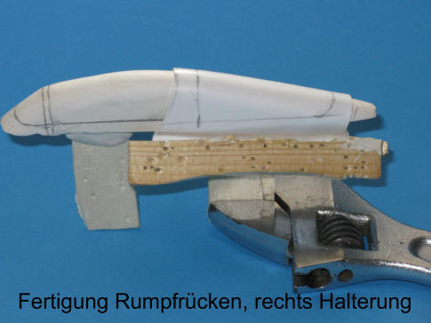
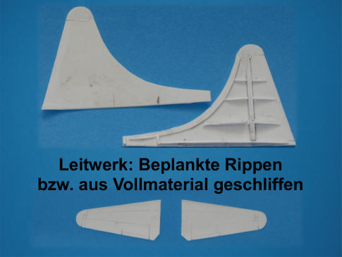
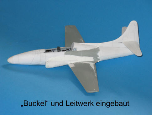
| "Hump" and empennage: The "hump" behind the cockpit was made in the usual way. The vertical tail consists of thin plastic with internal ribs (for wings I'd have used a balsa wood core), the rear edges thinned down to get a sharp trailing edge. The horizontal tail parts were made of plastic in appropriate thickness carved and sanded to form. Rudders, trim tabs and panel lines engraved afterwards. | ||||||||||||||||||
|
||||||||||||||||||
|
|
||||||||||||||||||
|
||||||||||||||||||
|
||||||||||||||||||
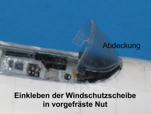
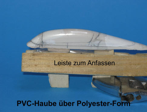
| Cockpit hood: Again no need to carve and sand a wooden block! Once again the form was made of polyester putty (used for both the canopy and the hump to get an even transition). Making a new cockpit enclosure was mandatory as the one of the Sea Star had a rounded windshield and the rear part was higher. As freshly mixed polyester paste tends to flow a little bit a tub was needed to get the exact cross-section of the to make canopy. For this clear PVC was laid over the cockpit opening, its planform marked onto the PVC. This was used as a template for forming the tub. For the canopy clear plastic (PVC) was needed this time, but otherwise the procedure is the same. See page C, "cockpit hoods". The windshield rests in a groove, for additional strength with a tongue in a narrow slit in the middle. After the part to remain clear was covered with clear tape it was glued in with epoxy glue (any excess wiped away). After this had dried small imperfections were filled with putty and sanded smooth. | ||||||||||||||||||
|
||||||||||||||||||
|
||||||||||||||||||
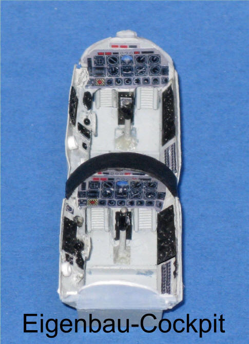
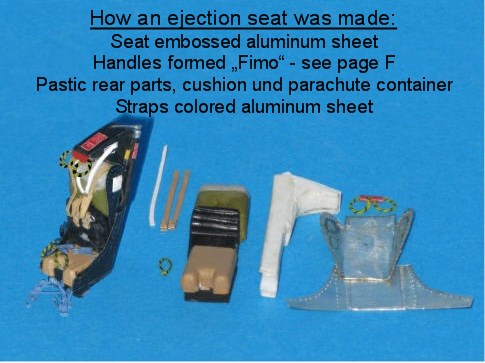
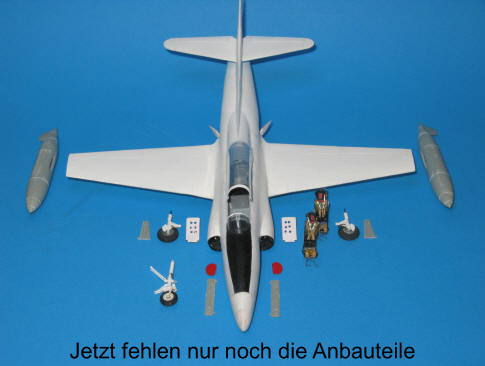
| Ejection Seats:
Real
ejection seat pans are made of thin metal sheet whereas in most cases model resin
seat walls are too thick, even more so in kit form. In effect in my case the
resin seats I had bought didn't fit into the cockpit tub.
So making them myself was inevitable. It's far easier than one may expect. Additionally
one avoids the labourious task
of painting some awkward details of resin seats. And, not to forget:
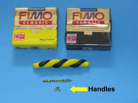
Ejection seat handles have black or yellow resp. red spirals not segments as usually
shown by models (see photos of original MB seats). How it was done can be seen in the lower right photo. All you need are blocks of "FIMO" plasticine. Knead a small amount of black and yellow respectively until soft and then form thin sausages. Place them against each other, twist them against each other and at the same time gently pull them outwards until the desired thickness (= thinness) is reached. Form a pretzel and place on a piece of sheet metal (e.g. from fast food tray). On top, as in the original, a piece of (red) FIMO across the open ends, which also helps in the later fastening. Heat the whole thing over a candle flame until steam / smoke rises. Then the part is firm but still flexible and can be installed with superglue. Marked handles then do likewise. |
||||||||||||||||||
|
||||||||||||||||||
|
||||||||||||||||||
|
||||||||||||||||||
|
||||||||||||||||||
|
||||||||||||||||||
|
||||||||||||||||||
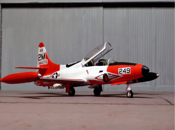
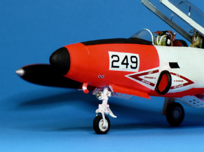
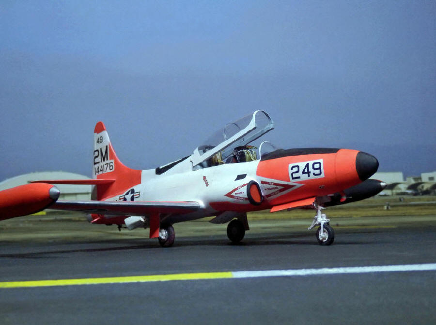
| Paint: The then standard paint scheme was "Insignia White" (FS 17875) and
"International Orange" (FS 12197). While white colour is to be found in
every modellers stock, I could not get "International Orange". As this
colour is darker than "Dayglo Red" I mixed Dayglo with dark red. In the
result I got the right shade but had a whole bunch of problems with it
(a second layer appears darker and so on). Sometimes the model was in danger
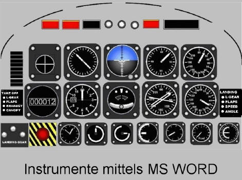
to end in the trash bin. Well, that's modeling. Markings: Markings for a T2V-1 of the Memphis Naval Air Station, as seen in "Ginter, Naval Fighters No. 42". Unlike seen on Sword's 1/72 kit, the last letter was not in the white field. Made by MS WORD on neutral decal paper for inkjet printing (inkjet printer on laser paper would not work). The national insignia was also made by myself, because it is usually shown much too blue in decals. |
||||||||||||||||||
|
||||||||||||||||||
|
|
General ideas and tips for modeling see "Modeling ABC"