|
|
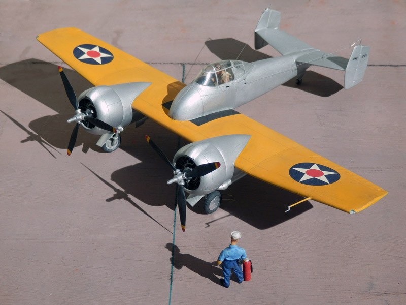
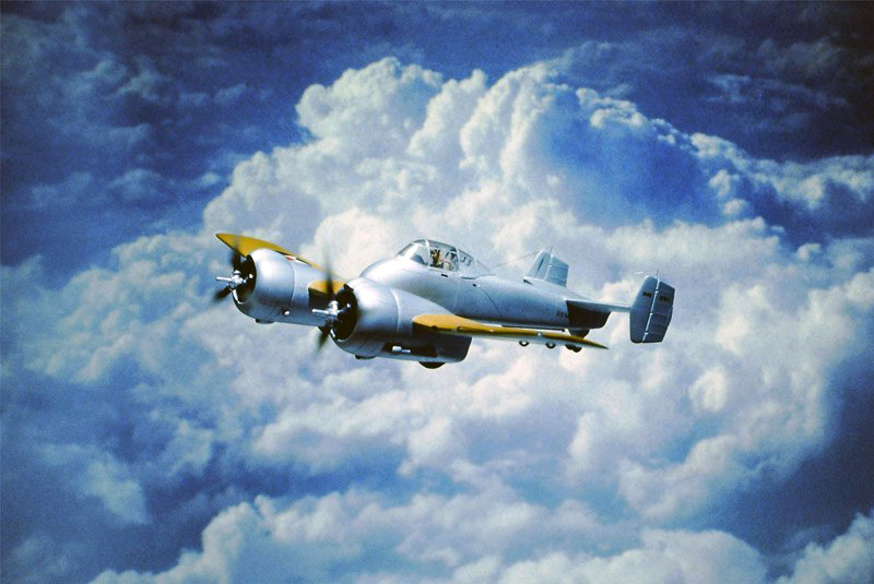
| F5F-1 Skyrocket, 1/48, 100 % scratch (no kit or other purchasable parts) |
| Model by Wilfried Eck | ||
|
||
|
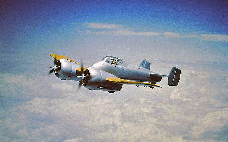
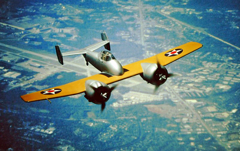
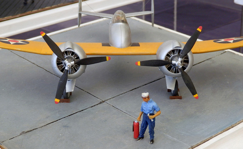
The prototype, which the U.S. Navy ordered from Grumman on June 30, 1938, under the designation XF5F-1, was revolutionary for its time. Fighters at the time were single-engine biplanes with two 7.62 mm MG. The Skyrocket was twin-engined, armed with two 23 mm guns (later 4 x 12.7 mm) and promised to be faster and more capable of climbing. A striking feature was the extremely short fuselage nose. The prototype, which had its maiden flight on 01.04.1940, seemed to confirm all predictions, but subsequently revealed cooling and, above all, landing gear problems, so that despite various modifications it never went into series production. When the project was discontinued in 1944, however, the knowledge gained had already been put to good use in the F7F Tigercat, which was now under construction.
|
|
|
The model
In 1993 there was no kit of the F5F-1 Skyrocket available. In such a case, the
experienced modeler used to look in his "grab box" for usable parts and/or
cannibalize other models. Since I didn't find anything useful at my place, that
would have meant having to buy two Monogram F4F Wildcat kits for the propellers
alone. But if you were able to make cockpit canopies yourself (without balsa wood
blocks), you should be able to put together the fuselage and engine nacelles. I
thought so and decided to make it 100 percent right away to show that it can be
done without butchery. Seems difficult, but it wasn*t at all. As a result, it
required thought and patience, but it was also a lot of fun. To prove that such a thing is possible, in the required brevity:
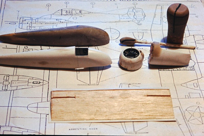 |
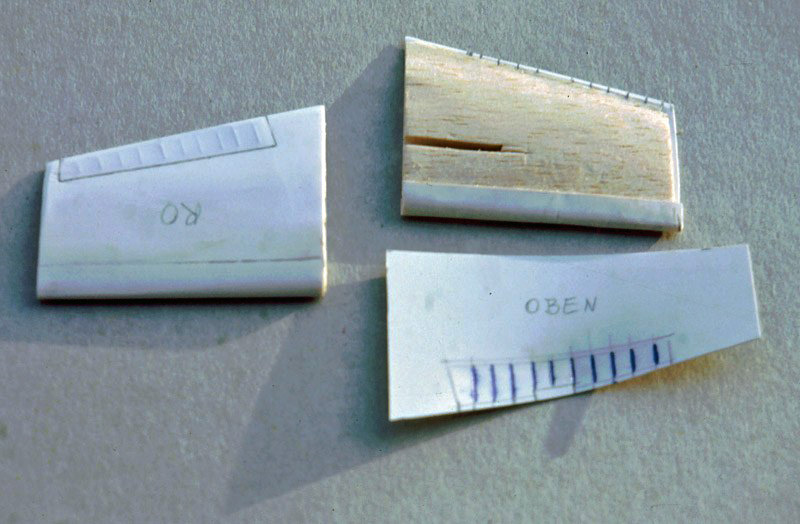
Construction stage 1
In the background the plan, scaled to 1:48 minus material thickness of the
plastic. On the top left the mold for the fuselage made of polyester putty, on the right the molds for the engine nacelles.
Why there are still people today who think you have to carve balsa wood for a mold, I don't know. Nowadays there is polyester putty, to be found in hardware stores at car accessories, which, after 4 % hardener begins to take effect, can already be roughly cut to size and, after complete hardening, can be sanded and polished to a high gloss (alternatively I could have used "FIMO" modeling clay, however, you cannot apply a second layer here if you have made a mistake).
In front of this, the already finished parts. The plastic had first been softened over a toaster and then pulled over the mold in a smooth motion. A parting line drawn on the mold part and a scalpel helped to remove the excess. Strips glued on the inside help to join the two parts (i.e. see T2V-1 model). Below you can see the center section of the wings, profiled balsa, already planked in front and below, recesses for angled parts to attach the outer wings.
The cockpit canopy of clear PVC, not visible here, was made according to the same principle (see also modeling ABC page C"). As far as handling when "toasting" is concerned, two strips fastened with thumbtacks are sufficient for parts that only need to be slightly deformed; with others, such as the F5F cockpit hood here, is better to cut out the horizontal shape of thin plywood with a little allowance for the thickness of the material of PVC, and then fasten this part with thumbtacks. After heating both sides over the toaster (if it becomes limp, the PVC is sufficiently soft) then pull the plywood frame - PVC down - over the mold with even pressure. If you have already attached a "foot" at the bottom when building the mold (material unimportant), the hands have enough space down when pulling.
 |
Construction phase 2
Construction of the wings: Core balsa, planked with thin plastic, thickness
about 0,3 mm. First, the
nose section was formed, i.e. plastic attached to two leads, softened and placed
around the wing nose; excess cut off, then attached with superglue. For the
following parts, after the trailing edges had been sanded thin, it has to be
fast, because the trailing edges get a thin layer of plastic glue, but the rest
of the insides gets superglue.The edge pieces are
clear polystyrene, saving the need to insert the lights separately. Reproducing
the fabric covering was easy: mark the ribs on the inside and then emboss them
with a ballpoint pen, mark the rudder contour on the outside and engrave it
after planking. Sheet metal joints very fine lines, drawn with the tip of the
scalpel. That's all there is to it. Real covering is as taut as a
drumhead and does not sag at all in a wave-like manner.
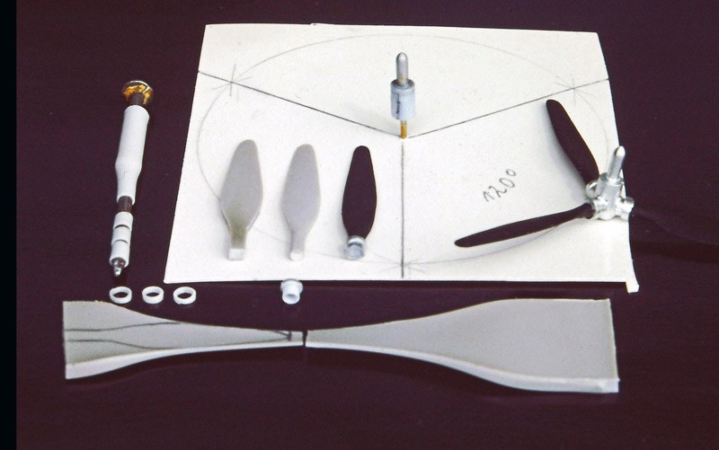 |
Construction phase 3
The photo above shows how the propellers were created (the finished part on the
right). For the propeller blades, plastic of suitable thickness was carefully softened
over a candle flame. After a second or two to cool down, pull both ends apart
and twist them slightly against each other. In this way, the propeller blade not
only becomes thin to scale towards the tip, but also receives the usual pitch of
propellers, i.e. the setting angle is greater at the hub than at the tip (zero
there). Using a template, mark out shape, cut out and profile. The fixing
clamps are parts of a tube stretched thin to scale over a nail. The hub is made
of a thinner drawn casting branch with interlocking tubes over it. That's it.
Almost a piece of cake, no resin part, no model stripping required.
 |
Construction stage 4:
Engines, hoods, nacelles: Unfortunately I did not take pictures of how the engines
were built. Nowadays everybody would use a resin part, therefore only in short
form told: Cylinder: The plastic core is wrapped with a thin strand of copper
wire (fixed at the back); push rods plastic tube, ignition cable copper wire
again. The front gear case was drill ground from solid stock (attached to a bolt
with nuts). Increasingly thin tubes were then inserted into the hole as a guide
for the pin axis of the air screw. This took a lot of patience, but the result
was better than any resin part.
The construction of the engine nacelles was basically the same as the construction of the fuselage, but the engine cowling and the rear part were built separately. The engine cowling is composed of the front ring and two semicircular parts behind it. The air scoop placed on top and shaped as usual was made to fit below by rubbing on the sandpaper placed on the cowl. The same was done with the engine nacelles, but here a roughly matching part was cut out in advance.
 |
Construction stage 5
The main landing gear, added after the "flight shots", is composed of a cranked
and suitably elongated nail with a tube and attachments, because metal looks
better than painted. For the wheels, plastic of a suitable thickness was first
roughly shaped, then fastened in a drill with screws and nuts and ground into
the shape of the wheel using the circle drawn. Another circle inside indicated
where the transition from the tire to the hub had to be worked out with the
scalpel. After the tires were painted, detailed discs were applied inside and
out. The rear wheel was made from a ball of "FIMO" modeling clay, first pressed
a little bit flatter, then the tire and hub were reproduced with the help of a
gently pressed tube.
The pilot is self-made except for the head and hands of a Verlinden figure.
Likewise for the mechanic. The
antenna is a thinned-out thread of a pair of pantyhose (derived into the
fuselage side half thread thickness, laid over it and fixed in the fuselage by
means of a plug). In stark contrast to thinly drawn casting rod that breaks off
at the latest with the first dusting, something like this is not only
insensitive to touch, but lasts forever. So don't turn up your nose, but try it
out. Due to lack of reference photos and because you wouldn't be able to see
much anyway because of the pilot figure, I didn't bother with fictional details,
same with the landing gear wells.
Colors: Humbrol 99 "Aluminum", "Orange Yellow" Yellow slightly tinted with Red; Engine: medium gray cylinders, aluminum pushrods, dark gray gearbox.
About the photos: All "flight shots" on slide film, so not
post-edited. General thoughts and tips for modeling see "Modeling ABC"
 |
![]()